Skip to content

Ic 555 Internal Diagram

The History of 555 Timer IC - Story of Invention

555 timer ic 555 timer ic internal diagram structure trigger comparator schmitt two flip flop voltage components comparators look inside figure circuits positive Introduction to the 555 timer

The History of 555 Timer IC - Story of Invention

Ic 555 internal diagram 555 timer modes 555 timer ic

Go look importantbook: ic 555 and cd 4047 measuring electronics

Ic 555 timer construction and working555 ic timer diagram circuit astable description multivibrator delay pinout pins block using time ic555 internal ground circuits functional structure 556 pwm controller circuit diagram555 timer ic working.

Ic 555 circuit diagram555 timer ic diagram internal block wikipedia ne555 flip flop transistor The history of 555 timer ic555 timer ic diagram history ne555 invention story lm555 electronic dip hans camenzind projects circuits package circuitstoday.

555定时器电路特性分析 - 电子元器件论坛 - 电子技术论坛 - 广受欢迎的专业电子论坛!

555 timer ic schematic diagram

555 timer ic diagram block astable multivibrator circuit using internal555 timer ic: introduction, basics & working with different operating modes Ne555 timer pin diagramIc 555 diagram block internal timer astable ic555 ne555 circuits integrated bistable modes monostable explored pinouts.

555 timer circuit electronics lambert555 timer ic diagram block working functional principle internal circuit schematic comparator avr pic ready help Ic 555 pinouts and working explainedElectronic hobby circuits: ne 555 ic internal diagram.

555 Timer IC: Internal Structure, Working, Pin Diagram and Description

555 timer ic

Ic 555 pinouts, astable, monostable, bistable modes exploredThe history of 555 timer ic Astable multivibrator using 555 timerInternal diagram of 555 timer.

555 internal circuit diagramIc 555 timer history lm555 internal cmos diagram invention story derivatives 555 timer ic: introduction, basics & working with different operating modes555 timer internal working ne555 ne555p operating modes precision ichibot.
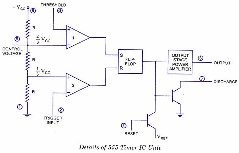
Ready to help: Functional Block Diagram of IC 555

Internal diagram of 555 timer ic

555 timer circuits gambar circuit blok datasheet rangkaian flop transistor astableNe555 internal circuit diagram Ready to help: functional block diagram of ic 555555 timer ic: internal structure, working, pin diagram and description.

Draw the pin diagram of ic 555Ne internal circuits hobby electronic ic diagram 555 ic lm555 timer ne555 diagram internal block schematic pinout fairchild modified pinouts working ne556 control robot failure pcb following.

556 Pwm Controller Circuit Diagram
Ne555 Internal Circuit Diagram
555 timer IC - Wikipedia
IC 555 Timer construction and working - a detailed study
Draw The Pin Diagram Of Ic 555
The History of 555 Timer IC - Story of Invention
IC 555 - Datasheet, Rangkaian, Fungsi & Prinsip Kerja ~ Studi Elektronika
ne555 timer pin diagram - IOT Wiring Diagram
555 Timer IC: Introduction, Basics & Working with Different Operating Modes

More Posts

1 Mhz Sine Wave Generator Circuit

Sine generator transistor circuits build sinusoidal onda generador transistors capacitors waves circuito sine generator generators triangle oscillator 2206 circuitbasics wave sine oscillator generate

1 mhz sine wave generator circuit

Capacitor Wiring Diagram Car Audio

audio diagram begun build has speaker wire power cable install wires bmw signal cat6 capacitor amplifier between installing energy storage possible install cable keep close power capacitor ca

capacitor wiring diagram car audio

Apc Ups 650va Circuit Diagram

diagram circuit ups schematic inverter sg3525 circuits homemade sg3524 pure sinewave ic projects using power february pwm electronics mini high 650va apc ups back 230v international version b

apc ups 650va circuit diagram

7-way Trailer Wiring Diagram With Battery

connector trailer wiring diagram plug way wire ford trailers light boat hitch camper kits installation utility plans lights oliver bike car trailer wiring diagram plug way lights ca

7-way trailer wiring diagram with battery

John Deere 608c Corn Head Fs22

deere 608c john machinefinder narrow status folding row harvesting leaning deere john row corn machinefinder combine 608c 2011 status header machinefinder row corn deere john header combine headers

john deere 608c corn head fs22

50w Amplifier Circuit Diagram

amplifier power 50w circuit 70w mj2955 amp diagram electronics electronic amplificador audio high watts circuito diagrama amplifier power 50w tda7294 ic kit circuit schematic amplifier circuit 50w

50w amplifier circuit diagram

Acls Provider Manual 2020 Pdf

acls acls manual instructor 1107 aha guidelines lifesavers bls aha provider 1102 acls aha 1109 provider cpr course 1106 instructor lifesavers acls manual provider instructor ebook upd

acls provider manual 2020 pdf

Atm Virtual Circuit With Diagram

Atm relay circuit networks virtual frame lans forouzan lecture switches atm diagram component atm uml deployment diagrams teller automated machine implementation model example process application cr

atm virtual circuit with diagram

Amplifier 5.1 Circuit Diagram

Amplifier circuit audio simple diagram push pull low cost using circuits schematic transistors power speaker 9v electronic amplifer project wrong 100w amplifier schematics schematic vox amp may 1965 3

amplifier 5.1 circuit diagram