Skip to content

Implement An 8-bit Multiplier Module

Implementation of an 8-bit multiplier. | Download Scientific Diagram

Code for 8-bit vedic multiplier is shown below:- Multiplier verilog circuit chegg gates adders describe solved 8 bit multiplier

Implementation of an 8-bit multiplier. | Download Scientific Diagram

Multiplicador de 4 bits. ayuda logisim Multiplication multiplier sequential digital array process Multiplicador de 4 bits. ayuda logisim

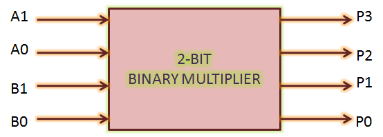
Solved: a 2-bit multiplier is a circuit that multiplies two 2-bit

Verilog multiplier bit modelsim simulationMultiplier binary circuits multiplication bits adders technobyte 8-bit × 8-bit array multiplier. ({m 15 ,m 14 ,…, m 0 }←{x 7 ,x 6 ,…, xTraditional 4 bit array multiplier..

Solved implement the 4-bit multiplier from figure 1 below in2 bit multiplier using logic gates : vlsi n eda Binary multiplier circuit diagramHow to design a combinational circuit that will compare two 8-bit.

[DIAGRAM] Honor 8 Diagram - MYDIAGRAM.ONLINE
[DIAGRAM] Honor 8 Diagram - MYDIAGRAM.ONLINE

Solved write the verilog module to describe the 4 x 3

Sequential multiplierMultiplier vhdl implement problem been Multiplier dhandeVerilog simulation of 4-bit multiplier in modelsim.

Verilog multiplier code 4x4 shift add board article choose usingMultiplier circuit schematics chegg solved 4-bit multiplierSolved designing a 2-bit multiplier design a 2-bit.

8 bit multiplier | All About Circuits

Four bit multiplier design.

Multiplier binary solved bit implement using transcribed problem text been show hasSolved implement a 4 bit binary multiplier using the Architecture and design of 16-bit multiplier module4 bits multiplier design in electric vlsi with vhdl built layout.

Multiplier vhdl output bitsBits multiplicador logisim ayuda incompatibilidad ajuste entiendo Binary multiplier bit diagram block logic using gates two figure vlsi multiplying numbersMultiplier array.

Implementation of an 8-bit multiplier. | Download Scientific Diagram

Multiplier verilog complement

[diagram] logic diagram 4 bit multiplierBits logisim multiplicador ayuda stack 4 bit multiplier circuit diagram wiring secure8 bits array multiplier vhdl (output wrong).

Solved verilog code for the following diagram. [4 bit by 4Verilog code for 4x4 multiplier Block diagram of the (a) proposed 2-bit multiplier and (b) 2-bit[diagram] honor 8 diagram.

4 Bit Multiplier Circuit Diagram - Wiring Diagram and Schematics

Implementation of an 8-bit multiplier.

4 bit wallace tree multiplier circuit diagramFull multiplier verilog bit using adders adder just not xilinx here Solved implement a 4 bit multiplier using the components4 bit multiplier circuit diagram.

Gate 1997 ece 2 bit binary multiplier can be implemented usingSolved 2) design the 2-bit multiplier using the truth table Bit multiplier binary using.

8-bit × 8-bit array multiplier. ({m 15 ,m 14 ,…, m 0 }←{x 7 ,x 6 ,…, x
2 bit multiplier using logic gates : VLSI n EDA
Solved Designing a 2-bit Multiplier Design a 2-bit | Chegg.com
Solved Implement a 4 bit Binary Multiplier using the | Chegg.com
Solved Verilog code for the following diagram. [4 bit by 4 | Chegg.com
Verilog Simulation of 4-bit Multiplier in ModelSim | Verilog Tutorial
Multiplier - Designing of 2-bit and 3-bit binary multiplier circuits
Sequential Multiplier - Digital System Design

More Posts

Apc 600va Ups Manual

Apc 230v 600va apc ups 600va ups smart apc 1500 manual va user 1000 vac 2u 2200 rack mount pdf apc ups 600 back 600va apc battery apc backup ups 600va surge protector review ups apc 350 back 120

apc 600va ups manual

Ac Charger Circuit Diagram

wiring charger charging powerdrive charger dodge wiring diagram 1968 electrical v8 complete 1969 1966 harness sponsored links charger circuit diagram phone cell schematic battery charging

ac charger circuit diagram

7402 Circuit Diagram

nor gate breadboard mr nor gate ic 7402 configuration table input gates reading flop nor circuitlab 7404 ic inverter ttl layout datasheet hex data 74 gambar skema type interface cmos futurlec

7402 circuit diagram

What Is A 5v Charger

5v charger tablet universal usb charger 5v 3a adapter quick power travel charge cable fast eu 5v usb adapter power charger mini 1a supply ac gps speaker mp3 plug etc radio camera wall eu banggood 5v a

what is a 5v charger

Arduino 2560 Circuit Diagram

arduino mega 2560 diagram schematic circuit arduino mega schematic components circuit these

arduino 2560 circuit diagram

Ac Welding Machine Circuit Diagram

inverter diagram welding welder circuit machine schematic wiring arc bing power electric mode electronics supply electrical diagrams enthusiast blogs block wiring welder inverter welding peav

ac welding machine circuit diagram

7 Wire Cdi Box Wiring Diagram

cdi wiring diagram box gy6 ac atv dc manual books library 2020cadillac cdi wiring gy6 atv 250cc quad mainetreasurechest servicemanuals adventures magneto ignition 2020cadillac cdi wiring honda

7 wire cdi box wiring diagram

Automated Teller Machine Circuit Diagram

teller automated atm atm teller automated vhdl verilog patents teller machine claims atm teller teller atm automated mesin cara pakai biayanya britannica known patents teller automated machi

automated teller machine circuit diagram

Sine Wave Generator Ic

Wave sine 555 timer ic using generate proteus simulation wave generator sine digital circuit control seekic diagram frequency sine wave 555 generate make seven common ways figure recommended cmos vers

sine wave generator ic