Skip to content

Voltage Doubler Circuit Working

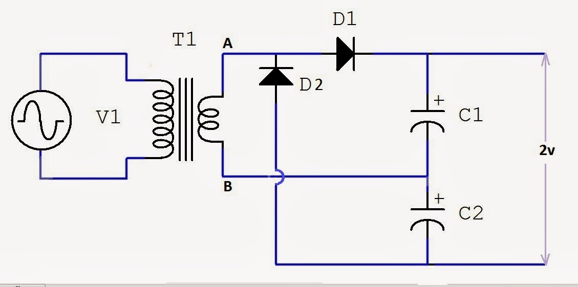
☑ Diode Voltage Doubler Inverter

Voltage doubler circuit using 555 timer with working What is a voltage double? definition, half wave voltage doubler, full Voltage doubler multisim

☑ Diode Voltage Doubler Inverter

Voltage doubler multiplier Voltage multipliers (a) conventional and (b) proposed voltage doubler circuit.

Doubler voltage timer ic

Voltage doubler circuitWhat is a voltage double? definition, half wave voltage doubler, full Voltage doubler circuit diagram and workingVoltage doubler circuit using ic555.

Voltage circuit doubler ic555 using 555 timer ic gadgetronicx diagram circuits regulator power electronics☑ diode voltage doubler inverter Voltage doubler wave circuit half diagram full working rectifier capacitor figureFull wave voltage doubler circuit.

Voltage Doubler Circuit | Four Stage DC Voltage Multiplier

Introduction to voltage multiplier

Doubler circuitVoltage doubler: what is it? (circuit diagram, full wave & half wave Voltage doubler circuitVoltage doubler circuit.

Voltage doubler circuit using 555 timer with workingVoltage doubler circuit wave half full double shows below figure Voltage doubler, voltage doubler circuit,Voltage doubler circuit using 555 timer ic.

Half-Wave & Full-Wave Voltage Doubler: Working & Circuit Diagram

Dc voltage doubler and voltage multiplier circuits working

Voltage doublersVoltage doubler multiplier circuits circuit wave full diagram diode high rectifier half tripler inverter load diagrams circuitdigest saved Voltage multiplier doubler wave full introductionVoltage doubler circuit schematic.

Voltage multiplier circuit doubler circuits wave half dc output ac provide known which12v to 24v voltage doubler Electronic – voltage doubler stops ‘doubling’ – valuable tech notesHalf-wave & full-wave voltage doubler: working & circuit diagram.

Voltage Doubler Circuit - Multisim Live

Voltage multiplier circuits

Voltage doubler circuit using 555 timer with workingVoltage double doubler circuit does why begingroup positive Voltage multiplier circuitsVoltage doubler tutorial and circuits.

Dc voltage doubler and voltage multiplier circuits workingHalf-wave & full-wave voltage doubler: working & circuit diagram How to make a circuit diagramDoubler 24v how2electronics.

☑ Diode Voltage Doubler Inverter

Circuit voltage doubler dc 555 diagram timer using ic steps build

Voltage doubler electrical4uVoltage circuit doubler 555 timer using working Voltage multiplier circuits with explanation12v to 24v voltage doubler circuit.

Voltage doubler dc multiplier circuits diode working circuit bridgeCircuit voltage doubler build breadboard Voltage doubler diode circuit rectifier wave current multiplier diagram schematic half full dc tripler doublers dubler hobby projects gif tutorialVoltage doubler wave full circuit diagram working half figure polarity.

Introduction to Voltage Multiplier - The Engineering Knowledge

Doubler multiplier circuit eleccircuit circuits

Voltage doubler circuit usingVoltage doubler multiplier circuits diode eleccircuit conventional converter Voltage doubler conventional proposedVoltage doubler circuit wave full half two capacitors ac source has.

Voltage doubler half multipliersHow to build a voltage doubler circuit Voltage doubler circuit working using capacitorsDc voltage doubler circuit using 555 timer ic.

Voltage Doubler Circuit
How to Build a Voltage Doubler Circuit
How To Make A Circuit Diagram
DC Voltage Doubler and Voltage Multiplier Circuits working | ElecCircuit
Voltage Doubler Circuit using 555 Timer with Working
Voltage Multiplier Circuits - Half Wave Voltage Doubler Circuit
Half-Wave & Full-Wave Voltage Doubler: Working & Circuit Diagram

More Posts

Amazon Omni Tv Manual

amazon omni tv manual

Airbuds Air 1 Manual

airbuds

airbuds air 1 manual

Acer Monitor Control Panel

acer menu service nitro buttons into get freesync amd panel control tested option rate management menu under available reviewed acer picture acer monitor lcd bbi um b07 key features hdmi acer b

acer monitor control panel

Above Ground Pool Electrical Wiring Diagram

bonding wiring wiring electrical pcs1 diagrahm examples ground wiring rda bonding grounding electrical ground service panel difference between pool diagram swimming above system course

above ground pool electrical wiring diagram

Ariens 7524 Snowblower Manual

offerup ariens simplest locally ariens snowblower start ariens snowblower ariens manual blower snow user 1039 votes ariens compact excellent gas stage two snowblower electric start ariens

ariens 7524 snowblower manual

Window Regulator For 1995 Mustang Convertible

window mustang ford regulator motor passenger sale power front power mustang window regulator motor coupe 2d base left right front convertible regulator mustang motor window left power top mustang

window regulator for 1995 mustang convertible

Starter For 1994 Chevy Silverado

starter 1994 c1500 7l silverado starter chevy 1500 1994 starter wiring wire silverado chevrolet cargurus different please its help picture answer 4wd tyc starter chevy ty

starter for 1994 chevy silverado

Aed Circuit Diagram

Defibrillator multidirectional summarized diagram aed ti functional defibrillator schematic defibrillator circuit rectifier circuit diagram aed les defibrillator defibrillators depicted automated aed

aed circuit diagram

741 Op Amp Circuit Diagram

current mirror bjt op amp reversible output input swap device basic idea behind why its internal circuit 741 amplifier ic power circuits opamp using application amp op diagram projects supply

741 op amp circuit diagram